AdBrite

Your Ad Here
Showing posts with label technology. Show all posts

Monday, February 2, 2009

Quality Refurbished CT Scanners


Atlas Medical Technologies is a refurbisher of quality used CT scanners and used MRI equipment. As a comprehensive source for every facet of establishing a new imaging site, Atlas is unmatched in providing customer service, counsel and satisfaction on all refurbished CT and MRI scanner equipment and used imaging machines. With Atlas Medical Technologies, you'll have a seasoned partner who will guide you from site planning through installation. But it doesn't end there. Atlas backs each piece of imaging equipment we sell as well as our refurbished CT and MRI rental units, with an expert service team dedicated to sound equipment maintenance practices. You'll find Atlas is at your side, before, during and especially after the purchase of any imaging system whether it's a used GE CT scanner, mobile CT rental or MRI system. Visit our equipment pages or call your Atlas Medical Technologies consultant to determine the availability of your desired model and manufacturer of our refurbished CT scanners or new Philips CT systems.

Friday, January 30, 2009

Doctor blade for screen printing


In screen printing, flexible doctor blades are used for distributing the printing inks. They must be able to withstand a wide variety of stresses and strains and must also have good swelling resistance in contact with the ink solvents used in the printing industry. This is no problem for Vulkollan®, because it is free of fillers and plasticizers – a factor that contributes to its good chemical resistance.

With long printing runs, it is essential that the quality of the prints remains consistently good from beginning to end. Since the edges of the blades are subjected to considerable wear and tear, it must have very high dimensional stability. The high shear modulus of Vulkollan® and its low permanent deformation are key factors when it comes to ensuring consistent print results. In addition, the quality of the fabrics is rising all the time, increasing the strain on the blade material. Vulkollan's® high mechanical resistance ensures a long service life and considerably minimizes the work involved in subsequent sharpening.

This superior combination of properties – namely high mechanical strength and excellent chemical resistance – guarantees an extremely long service life even when the doctor blades are subjected to extreme conditions.

Sensor elements


To track down any corrosion damage or cracks in oil and gas pipelines, the workers use UCSD "go-devils" equipped with Baytec P sensor strips. Because Baytec P has such high elasticity, the sensor elements can always stick close to the pipe wall, even when they pass over pipe bends or travel through narrow cross-sections, thus minimizing measuring errors.
Other specifications made on the elastomer are particularly high resistance to wear and tear and outstanding swelling resistance.

Device for light therapy


A light therapy device that specifically activates the self-healing forces, relieves the organism and triggers regenerative processes has been developed by Bioptron AG in Mönchaltorf, Switzerland. The Bioptron 2 model works by encouraging cell activation, known as biostimulation of the cell. The housing of this device is manufactured by emaform AG, which is based in the Swiss town of Gontenschwil. The company uses the Baydur® 60 polyurethane integral skin foam system, developed by Bayer MaterialScience AG primarily for the production of technical housings.

On the look-out for a lightweight, tough and rigid material which would reproduce the complex design of the light therapy device perfectly, the choice fell on Baydur® 60. Because with its excellent flow properties, this polyurethane system has proved its suitability even for the production of large moldings with complex geometries. Thanks to its mold reproduction accuracy, finely detailed textures can also be rendered.

Another argument for integral skin foam system from BaySystems is that it forms a solid outer layer which, together with a two-pack polyurethane coating, produces a highly-resistant, easy-care surface.

Baydur® 60 also delivers the goods as far as economics are concerned. The parts can be made with inexpensive aluminum molds because the internal pressure generated in the mold is particularly low. Apart from this, the integral skin foam can easily be combined with other materials, which means, for example, that thread inserts can be pre- positioned in the mold and molded in place, considerably simplifying subsequent fabrication.

Helios movie projector


A cabinet can be far more than a handy, light and robust case. This has been proved by the Helios video projector and its sophisticated exterior made of Baydur® polyurethanes from BaySystems®. Available in a variety of colors, it is perfectly at home in its environment, whether at conferences or presentations.

The Helios digital video projector from the Italian company Vidikron Industries S.p.A. has a special visual appeal in more than one sense. The highly sophisticated electronics packed inside the set are protected by a cabinet manufactured by 2a.effe of Lissone, Italy, using polyurethanes Baydur® 60 and Baydur® 110 from BaySystems®. In addition to offering a perfect combination of design and functionality, these two materials also provide a number of structural benefits, including an excellent surface finish that is ideal for high-grade coatings and gives the projector a distinctively elegant appearance

Thursday, January 29, 2009

H-Bridge for Robots with High Current DC Motors


DC Motors which need high current and high voltage usually give high velocity and high torque. For small robots like line follower robot or fire fighting robot, I think IC motor driver L298 (up to 2A total current) is better choice. While for large and heavy robot, you need high current DC motors also H-Bridge suit to your DC motor.

This article sould be useful for you to build high current H-Bridge. H-Bridge schematics provided…

============================

The H-Bridge is the link between digital circuitry and mechanical action. The computer sends out binary commands, and high powered actuators do stuff. Most often H-bridges are used to control rotational direction of DC motors. And unless you buy a potentially expensive motor-driver, you need an H-bridge to control any robot with a motor.

This is a quickly sketched H-Bridge circuit with supporting circuitry.
H-Bridge

First lets talk about what a transistor is. These nifty chips revolutionized the electronics industry and you would be hardpressed to find something electronic that does not have at least a few thousand of these in them. So what do they do? They can control a flow of electrons by applying a voltage to them. The plumbing equivalent would be a water valve. By rotating the valve, a very large flow of water can easily be controlled.

MOSFET, Transistor
There are several types of transistors, such as the PNP and NPN, but for sake of making your life easy I will only talk about a MOSFET (Metal-Oxide Semiconductor Field Effect Transistor). These neat things have only been around for a decade or two, but are way better than the more traditional transistor. First they are more efficient. They are easier to calculate mathwise. Plus they usually have built in protection diodes so you don’t need to add them in later. They even have PWM (explained later) optimized MOSFET’s.

So to operate a MOSFET, you apply a voltage to the gate (from your microcontroller), and suddenly a current of electrons passes through the other two pins. Connect a motor (M) in line with one of the pins and your robot is set to go. In the above schematic you will notice the letters A and B. These are your two control lines which you apply this logic voltage to. Since you have two pins, and only a binary control, there are four possible things that can happen.

A=0 B=0 : Nothing happens, the motor is turned off
A=1 B=0 : Motor rotates clockwise
A=0 B=1 : Motor rotates counterclockwise
A=1 B=1 : Your circuit explodes into pretty sparks

Here is a ghetto visual graphic of the H-bridge logic chart:
H-Bridge A

H-Bridge B

So now lets talk about how to operate the MOSFET’s. Basically all you need to do is attach the gate to your digital output of your controller. When the digital output is turned on, 5V will be applied to the gate, turning the MOSFET on. However it is better to amplify that 5V to a value higher and I will explain why. The gate voltage controls the MOSFET internal resistance. Zero voltage makes the resistance too high for it to work. A very high voltage has a very low resistance. Resistance leads to loss of energy thermally. This means your MOSFET will heat up and possibly burn out. Take a look at the MOSFET picture above and you will notice my finger print in it. That is what happens when you touch a hot MOSFET - pain! So although you do not need to amplify the gate voltage, it is best to do so. You should also put a heat sink on it.

Square Wave for Pulse Width Modulation PWM
Ok so what if you want speed control, and not just an on/off switch? PWM! Pulse width modulation. PWM is when you send a square wave at a certain frequency to control the MOSFET as shown above. Basically you are telling your controller to turn on and off the motor at very high rates. So through inductance the motor is neither fully on or fully off, but somewhere in between. Such as at a slower speed. Also a note that motor torque, under PWM, remains the same whether fully on or only a percentage on. However, varying voltage for speed control reduces torque. So with PWM you have maximum torque yet slower speeds! You will have to experiment with wave length for both on and off periods, as well as frequency, to optimize your speed control. But a guess usually works.

Make sure the MOSFET you have has built in protection diodes. If not, install them on your circuit as shown. This is to prevent back currents from your DC motor. Also do not forget to put a small capacitor across the leads on your motor to reduce electronic noise and increase motor life. You might also want to refer to the tutorial on robot power regulation to help you design a better power source for your H-bridge.

It is also recommended to put a slow blow fuse after the power supply, resistors of a few 100 ohms on the gate logic, and the additional capacitors on your circuit as shown. This will prevent melting, large voltage surges, and high frequency emission.

Robots In CIS Applications

Robots have started receiving greater attention in medical/surgical applications. Tasks beyond human manipulation/precision capabilities are being trusted to assitant systems that only perform that small portion of the procedure, under human supervision. Despite intial skeptical response due to safety, and cost concerns the role of robots in surgery is likely to grow.

Surgical robots present an environment unlike most other applications where robots are applied. e.g. industrial plants. Mechanical components of surgical robots tend to be simpler, slower than their industrial counterparts, but the electronics, safety, and guidance systems are usually far more complex. A set of complex planning, guidance, and safety systems (often redundant) are involved in operating a surgical robot.

A team designing a surgical robot is faced with several difficulties. A complex system takes several years to develop, and development is often sequencial. E.g. The guidance system can not be tested until the hardware is available, and software developing and testing is highly dependent on availability of functioning hardware. Surgical robots are developed to deal with specific surgical procedures, and so each application results in the repetition of the design cycle.

A modular system allows software development to be independent of hardware design. It also allows existing modules to be used for new applications. It improves design clarity and testing and finally develops interfaces making interoperability between different systems easier.

There are several ways to develop modular/flexible software to control a robot: use/develop a programming language with all the facilities of object oriented design. But this would create yet another language, with a learning curve and user acceptance issues. An alternative approach is to develop interfaces, and implementations of the same in an acceptable programming language. This provides libraries that can be shared, swapped, and developed independently of each other. Furthermore, it allows the programming language to be changed, while preserving the interfaces (most programming languages provide ways of calling other language libraries, if need be).

The modular robot control(MRC) library is one such library. While the set of robots under consideration is mostly serial manipulators, the interface design can be easily extended to parallel architectures. The interface design is independent of the programming language, and the first implementation uses C++ classes. The library classes have a layered structure, each new Layer inheriting significant functionality from its parents.

This documentation is for the MRC library version 1.1 The class most commonly used by an application as an instantiable robot is the mrcRobot class and this should also be the base for all derived robot classes. Detailed implementation documentation exists separately.
s.

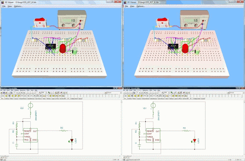
Live 3D Breadboard


Using the Live 3D Breadboard tool in TINA, you can automatically build a life-like 3D picture of a solderless breadboard (sometimes called a “whiteboard”). When you run TINA in interactive mode, components like switches, LEDs, instruments, etc. become “live” and will work on the virtual breadboard just as in reality. You can use this capability of TINA to prepare and document lab experiments.

You can either assemble the circuit step-by-step or by generating the whole circuit on the breadboard. Pick up and move parts on the breadboard using the mouse, and TINA will automatically rearrange the wiring while retaining connectivity. In the same fashion, you can select and move wires for clearer appearance. Note that you cannot change the endpoints of a wire this way–wiring integrity is preserved.

The breadboard tool is mostly intended for educational purposes to prepare laboratory experiments in a safe 3D environment. You can also use this breadboard to guide you in actually wiring a physical breadboard for lab verification.

Microsystems for Medical Technology


Social demand is the driving force for new developments in miniaturised medical technology. Well-informed patients have high requirements in terms of improving the quality and safety of their lives. That can be achieved by a marked miniaturisation of medical devices, instruments and sensors that ensure that patients have less traumatic operations or can benefit from mobile monitoring systems. Microsystem technology provides potentials that meet those new social and medical requirements to the point. Major applications of microsystems are, for example, intelligent implants, patient monitoring and minimally invasive technologIntelligent Implants

A very important field in medicine is the development of intelligent implants based on microsystems technology. The pacemaker is a wellknown example. The new generation of devices do no longer stimulate the heart by inflexible, constant impulses only, but collect data like heart rhythm and react self-sufficiently with variable adjustments. In this way, this therapy is becoming more flexible and physiological. Meanwhile these systems can absolutely hold their own on the market. Implanted defibrillators that stimulate the heart directly in case of cardiac arrest have also been developed. A strong electric impulse restores the heart function. These devices are also successfully being introduced into the market. The leading German supplier in that field is the company Biotronik GmbH & Co.

Patient monitoring

A second very interesting application for microsystems is the continuous monitoring of physiological patient data. Therefore sensor systems inside or outside the body are needed. Up to now only stand-alone solutions are available, that means data remain stored in the device. Examples for ambulant devices with limited storing potential are 24-hour-bloodpressure measurement or 72-hoursblood sugar measurement. Using miniaturised sensors future systems in domestic surroundings should measure continuously and precisely blood pressure, intraocular pressure, electrocardiogram (ECG), level of blood sugar or respiratory sounds. The collected data will be wireless transmitted to the physicians. In this application field German companies like Siemens AG Medical Solutions, Dräger Medizintechnik GmbH, Philips Medical Systems, Weinmann GmbH, Fresenius Medical Care AG und B. Braun Melsungen AG play an important role.

Minimally Invasive Technology

Minimal invasive operation techniques would be unthinkable without microsystems technology. In this field microsystems in terms of miniaturised mechanical and optical systems were introduced to the operating rooms already 15 years ago. German companies like KARL STORZ GmbH & Co. KG, AESCULAP AG & Co. KG und Richard Wolf GmbH are international leading players in this market with endoscopes and intelligent instruments. In future miniaturised instrument systems will be improved by sensors generating tactile feedback to the operating surgeon. Based on this tactile feedback, navigation systems can support the surgeon in planning and operating.

German medical technology is in a good position internationally

Internationally, German companies rank among the leading suppliers of microsystems in medical technology. They play an important part in the worldwide turnover in this market segment ( 12 billion in 2002) [1]. Microsystem technology is a key technology for the development of innovative medical products. Its great importance helps to strengthen the medical technology industry in Germany. In 2004 the total turnover of this industry sector was 18 billion Euros, employing 100,000 people in 1,200 companies [2]. Because of highly increasing exports, a turnover of 25 billion Euros is expected in 2010 [3]. "Made in Germany" is still a good reputation for medical products. The share of the turnover in foreign countries is almost 55% and it is expected to rise steadily until 2010 [4]. This underlines the international competitiveness of the German medical technology industry. With 38% of all exports, the EU states are the main customers of medical technology from Germany, followed by the US with 20% [4]. Two German companies belong to the worldwide top ten: Siemens Medical Systems ranks fifth and Fresenius Medical Care AG seventh [4].

Beside industry, national research institutes are a guarantee for success. More and more of them are combining R&D in microsystem technology with biomedical engineering. Wellknown representatives are IMTEK, Prof. Stieglitz, University of Freiburg, ITIV, Dr. Stork, University of Karlsruhe, IWE, Prof. Mokwa, RWTH of Aachen, and Fraunhofer IBMT, Prof. Fuhr, St. Ingbert. University hospitals like the Charité in Berlin, Erlangen- Nürnberg and others apply biomicrotechnologies for innovative solutions in diagnostics and therapy.

Future developments will imply new challenges The main challenge to be coped with in the field of microsystem technology is the connection of technological components with the biological surroundings. In future, top innovations can be achieved in the following applications:

* Enhancement of active implants by biocompatible coating
* Intelligent drug targeting according to data determined by microsystems
* Linking of data for complex diagnostics in an environment close to the patient without necessarily consulting a physician or going to hospital
* More complex and individual analysis of biological, chemical, pharmacological, toxicological and medical data .. Continuous advancement of imaging systems for instrument navigation and better acquisition of parameters relevant to therapy

Wednesday, January 14, 2009

ST Launhes Combined Audio Processing And Amplifier Chip

Wednesday, January 14, 2009: STMicroelectronics has introduced a combined audio processing and amplifier chip with enhanced features to increase performance from compact home-audio equipment. The STA339BWS is optimised for applications using small, low-cost speakers, such as flat-panel TVs and docking stations

Digital audio techniques, such as signal processing and class-D power amplifiers, enable smaller systems to deliver high-quality room-filling sound that would be impossible with traditional hi-fi technologies. However, manufacturers are under constant pressure to deliver improved listening experiences from ever smaller and lower-cost equipment. ST's Sound Terminal digital audio ICs answer these challenges using techniques such as Full Flexible Amplification (FFX) enabling a fully digital stream from sound source to loudspeaker. In the application, this produces improved audio performance, reduced cost and smaller size, ST claimed.

As the latest addition to the Sound Terminal family, the STA339BWS combines IP from ST's audio processing and class-D power amplifier ICs into a single chip, and includes advanced features such as MultiBand Dynamic Range Compression (DRC). DRC uses the latest sound-processing algorithms to enhance the performance of low-cost speakers and also prevents large bass signals from causing vibrations and damaging small speaker units.

Other important features include a seven-band equaliser. By offering two more bi-quads than common five-band equalisers, the STA339BWS improves speaker response and shaping of sound effects. A further advantage is continuous audio streaming when changing channels or audio sources, which saves muting the output to suppress noise during each transition. The output is configurable to deliver 2x20W stereo into 8-Ohm speakers or 2.1 channels at 2x10W plus 20W. This flexibility allows one hardware platform to serve several different products.

"The STA339BWS is the industry's first single-chip device to include audio power amplification and advanced DSP processing features such as MultiBand DRC," said Andrea Onetti, general manager, audio division, ST. "This powerful addition to the Sound Terminal family of digital audio ICs brings new functionality and higher performance, and delivers it in a smaller package, making it possible for leading home-entertainment equipment manufacturers to deliver best-in-class audio experiences for consumers."

By combining functions that previously required a multi-chip solution into a single device, the STA339BWS simplifies product design and assembly. The new IC is also pin-compatible with existing Sound Terminal ICs for flat-panel TVs, enabling easy design-in to next-generation products. Its high level of integration, compact footprint and high audio performance also benefit products such as docking stations and mid-power home audio equipment.

The STA339BWS is delivered in a compact PowerSSO-36 package and is priced at $2.50 in quantities of 10,000 units.